Coach’s Corner: Tackling a 600 fpm conveyor

Tackling a 600 fpm conveyor at 10 feet per second, you better have a plan
The situation:
Armed with one RFID reader and four antennas, we had to figure out how to get a 100% read rate on tagged items as they moved along a conveyor.
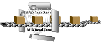
At first it seemed that the typical ‘box’ design would be a great idea. The fact is, however, placing four antennas over a read area is usually the worst possible design for nearly any RFID installation.
Coach’s considerations:
In the case of a conveyor, here are two very significant problems four antennas create:
(a) Limited Height: The over head antenna restricts the maximum box height.
(b) Redundant Antennas: The two side antennas on a less than four foot wide conveyor are unnecessary and lower the readability of cases due to lowering the number of tag protocols (Class 0 or 1) that can be performed during the limited read time available as a carton passes in front of the antennas.
In demonstration testing, the ‘four antenna box’ design works really well. But, not for the reasons you would think. The box design works because when you align the antennas to point at each other (top to bottom and side to side), they act as natural RF (Radio Frequency) reflectors and create a highly saturated RF read field. You can actually create a more effective RF read field with two antennas.
The solution we put into play:
After installing and testing dozens of read points, we developed the following criteria to consider for any read point:
1)Tag linger. How long will tags stay (linger) in the RFID read field?
2)Tag density. How many tags will be passing through your read field during a time-period?
3)Optimal tag position. What are the potential locations of a tag read? How is your read field designed to deal with those tag positions?
4)Tag types. How many different tag protocols must you check for during that time-in-field?
Based on the four criteria, here is how we determined the optimal method to develop a read point.
Step 1: Determine tag linger.

Example:

Step 2: Calculate tag density
For dock doors, 100 to 200 tags may pass through a read field at one time. On a conveyor, assuming six inches of separation between items, and one foot minimum per item, the ‘tags in field’ would equal four items at a time.
Step 3: Determine number of tag protocols
Each antenna in your read point must send ‘who’s there’ commands to the tags moving through the RFID read field. Assuming you must parse Class 0 and Class 1 tags, you have to allow for two separate RFID ‘who’s there protocols’ to complete to capture all moving tags. Therefore, tag protocols = 2.
Step 4: Calculate minimum time needed per antenna to read a tag
Each antenna you install for a read point must be given time to scan every protocol you request. Note: RFID Antennas fire (scan for tags) sequentially. This is important. Each antenna must wait its turn to check for RFID tags. Repeat: Antennas work one at a time! This is critically important to understand. If multiple antennas transmit, you will have RF collisions and none of your tags will be read.
The ‘tested performance’ for tags we use:
•Class 0 = 110 ms (for up to 20 tags; more than 20 tags you must add 3 ms for each additional tag so, for example, 21 tags would require 113 ms)
•Class 1 = 15 ms per tag
Typically, on a conveyor, this means you must allot 170 ms time slice (assuming your ‘tags in field’ will always be < 10) because the class 0 protocol takes 110 ms to allow for sequencing.
Now, we can determine the minimum read time needed

Example:

Step 5: Determine the number of antennas needed
If you use four antennas, your minimum Tag Linger must be four times step number four, the minimum time needed per antenna to compensate for the worst-case positioning of tags. This means, using four antennas, you must be able to see the tag for 680 ms (170 ms x 4 tags) to ensure each antenna will be have a chance to acquire the tag (assuming only ONE of those antennas is positioned to accurately read the tag).
As you can see, without using any Velcro or industrial tape, we know mathematically this read point will fail. We have a time requirement of 680 ms for this read field to achieve a 100% read rate, but according to Step 1, we only have a 500 ms window to read the tags.
The alternative are:
a) We can reduce the number of antennas
If we drop to three antennas, our time required is 3 x 170 ms or 510 ms. There is a very slight overage there and will amount to a potential slippage of 1% tag miss due to poor read point design. Two antennas get us to 340 ms – well under our time threshold. Two antennas is a great place to begin your test because we accomplish a 50% read overlap (each antenna gets to read almost two times per carton) so we get an additional shot at reading the tags as they pass our read RFID point.
b) We can reduce the conveyor speed
This is not a viable alternative since it will slow down production.
c) We can reduce the number of tag types
For a single tag type (Class 0 or Class 1 only) solution, there is no problem with four antennas because the reader doesn’t have to re-scan each antenna with a different tag protocol. A single protocol will be real when generation II RFID tags are available. However, think about this: Every install being deployed today will likely have to support generation II, Class 0 and class 1! This means: Most of the four antenna, 600-fpm conveyor installs will fail when Generation II ships because they will have to scan three protocols per antenna.
The Big Six solutions for metal, liquid or tissue
RFID Tagged items can only have their RFID tags placed forward, backward, up, down, left or right. That’s what we mean by the Big Six positions.
You can test the six ordinal tag positions with metal, liquid, and tissue. I can tell you now: Don’t bother with tissue – it always reads. Select metal or liquid as your test. Since most liquids are palletized / non-conveyed, your test should probably be limited to metal.
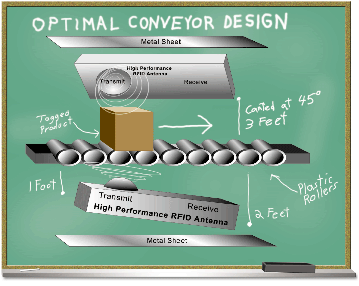
In our testing, the results are: Given a 6″ minimum gap and 4″ minimum ‘conveyor side guard rail’ separation, you will achieve 100% read with this configuration in the ‘big six’ at 600-fpm and two antennas.
Cool RFID Tricks
Metal acts as a ‘free’ antenna
The same problems metal causes also help us. Namely, metal stops the RF wave and sends it back to us. By placing a metal sheet under your conveyor, you create free ‘side’ antennas. A metal sheet within five feet of an antenna creates a mirror antenna on the side of the metal sheet. This is very handy because it lets us see the other side of metal or liquid items.
You should place a metal sheet under your bottom antenna and above your top antenna to create a ‘free’ top mounted / canopy antenna, and on the opposite side of your 45 degree angle mounted side antenna. Essentially, you will create a ‘metal box’ that will bounce the RF signal all over the target RF area.
Also: The metal RF reflectors should be facing the opposite antenna (not ‘angled’). Just like stealth airplanes using angles to divert RF, an RF signal creates the strongest reflection when the metal surface faces the incoming RF signal.
Bumpers increase your reads
Make sure your cartons are not touching the rails of your conveyors. Put a plastic bumper of at least 4″ to get the product off the side rail. An RFID tag touching the sides of the conveyor can not be read.
